MFC / GAS FLOW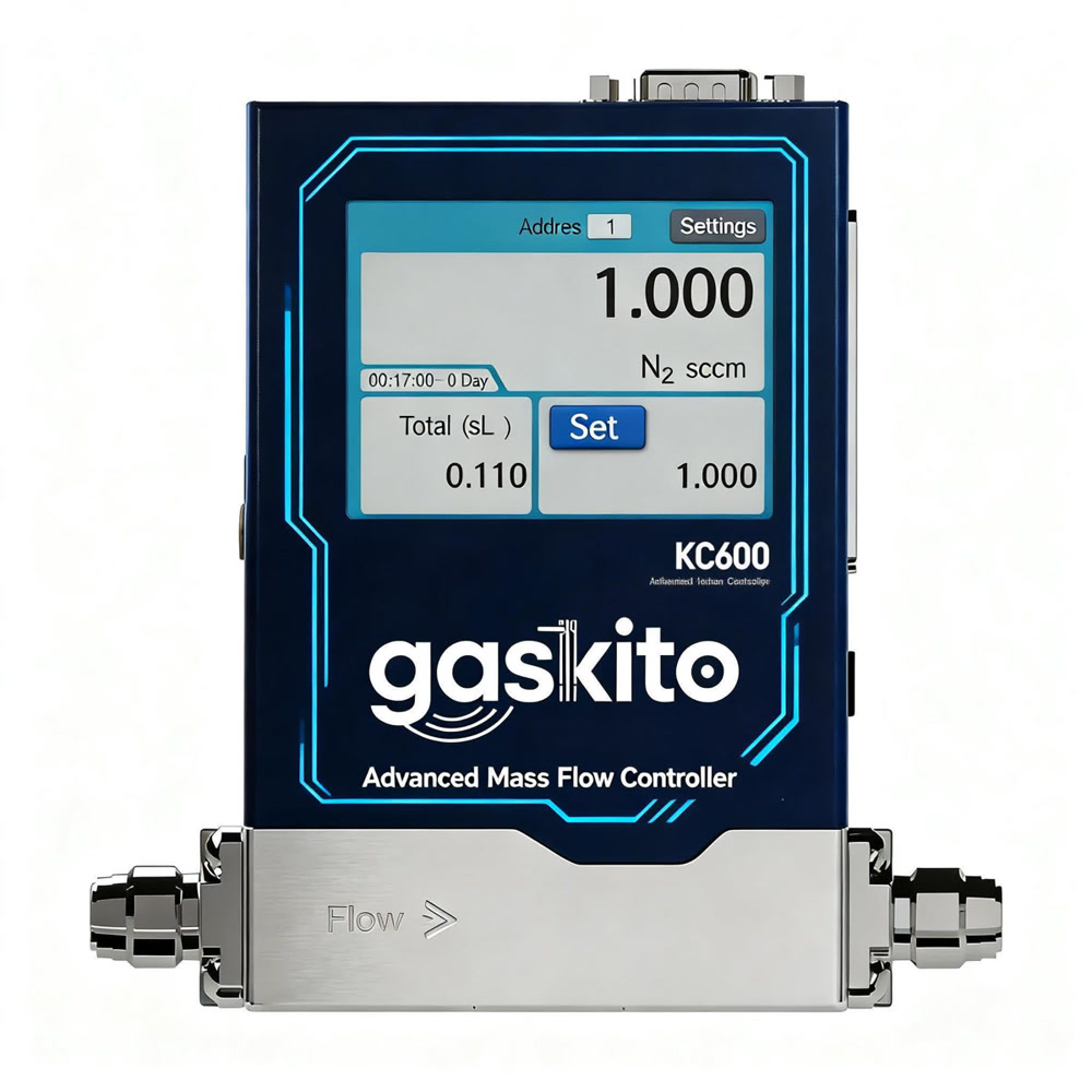
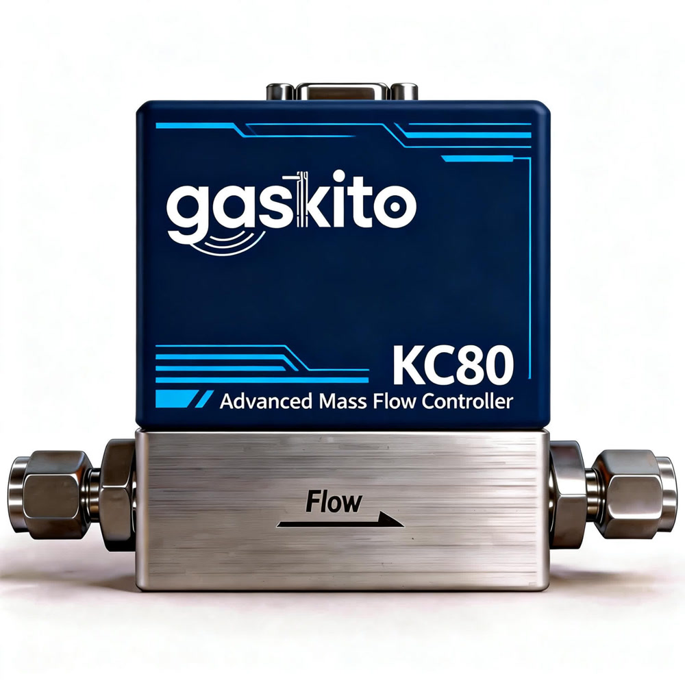
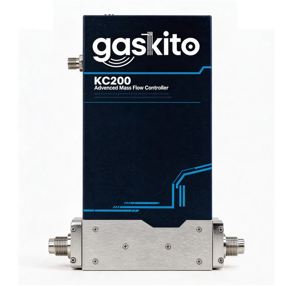
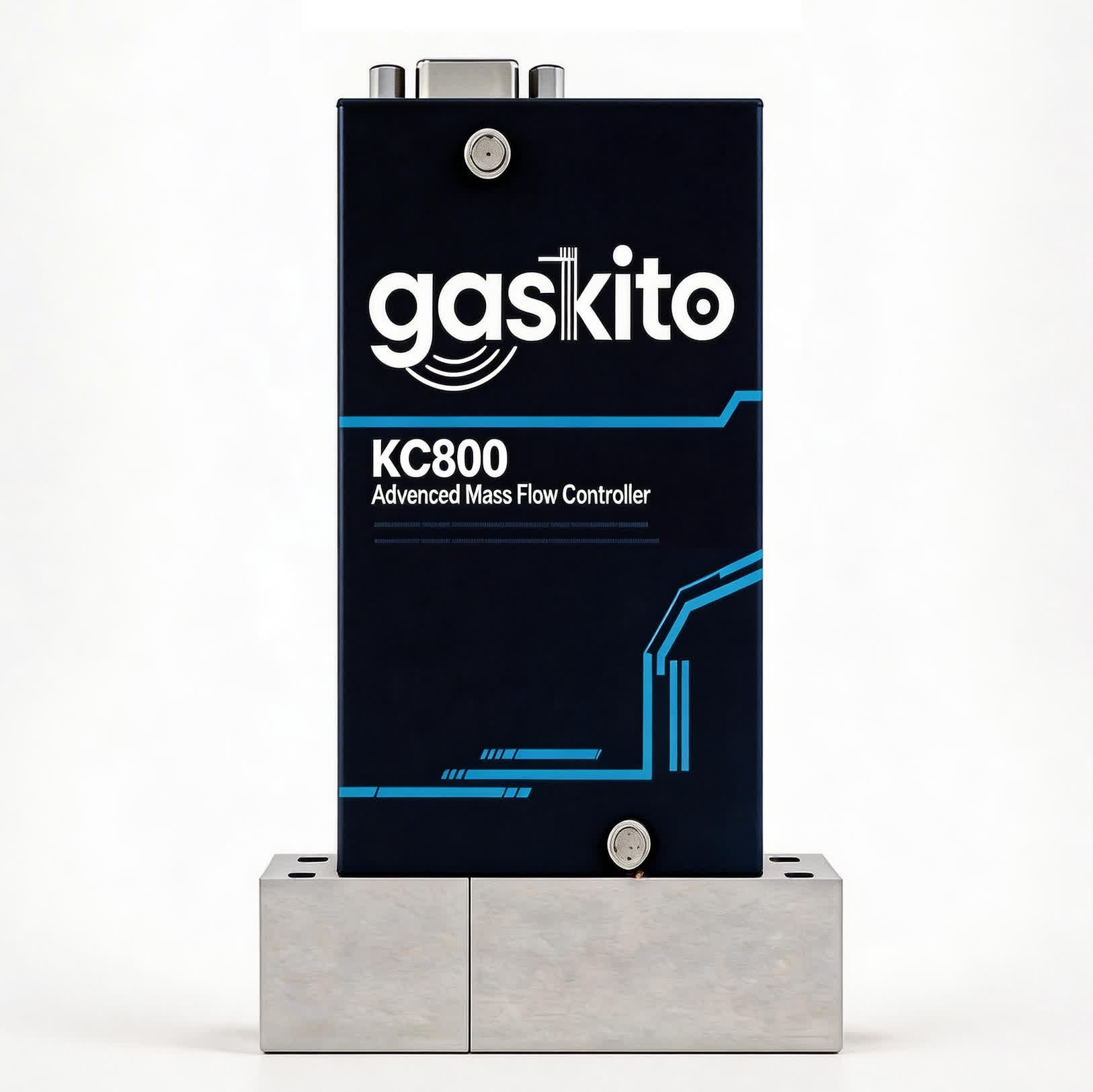
Product appearance varies by configuration.
Mass Flow Controller (MFC)
KC600 Series
The KC600 Series gas mass flow controller combines an industrial flow sensor with a dual display and an adjustable flow range. Configuration and monitoring are available through PC software. Typical applications include semiconductor processing, photovoltaic production, and vacuum coating.
- Range
- 0~20 sccm to 0~20 slm (nitrogen equivalent)
- Accuracy
- ±0.3%F.S. (≤30%F.S.) / ±1.0%S.P. (>30%F.S.)
- Turndown Ratio
- 100:1
- Response Time
- ≤0.5s
Configuration and suitability confirmed for your application.
Basic Parameters
| Media Requirement | Clean, dry, non-corrosive gas |
| Media Type | Air, nitrogen, oxygen, carbon dioxide, helium, hydrogen, methane, argon, etc. |
| Flow Range¹ (Nitrogen Equivalent) | (0~20, 50, 100, 200, 500) sccm (0~1, 2, 5, 10, 20) slm Other ranges customizable, please contact us |
| Accuracy | ±0.3%F.S.² (≤30%F.S.) ±1.0%S.P.³ (>30%F.S.) |
| Turndown Ratio | 100:1 |
| Response Time⁴ | ≤0.5s |
| Repeatability | ≤±0.2%F.S. |
| Resolution | 0.001 sccm, ≤20 sccm 0.01 sccm, ≤100 sccm and >20 sccm 0.1 sccm, ≤1 slm and >100 sccm 1 sccm, >1 slm |
| Leak Rate | ≤1×10⁻¹⁰ Pam³/sHe |
| Max Pressure Rating | 9.8bar |
Environmental Conditions
| Operating Temperature | 0~50℃ |
| Operating Humidity | 10%~90% R.H. (no condensation) |
| Working Pressure⁵ | 0.5~4 bar, >2 slm 0.5~6 bar, ≤2 slm (range dependent) |
| Storage Temperature | -20~85℃ |
Electrical Parameters
| Power Supply | DC24V |
| Power Consumption | ≤4.0W |
| Startup Time | ≤1s |
Communication Interface
| Interface Type | D-SUB9, RJ45 |
| Analog Control | 0-5V or 4-20mA |
| Digital Control | RS485 or RS232 |
Digital Signal (RS485/RS232)
| Interface Type | D-SUB9 or RJ45 |
| Baud Rate | 9600, 38400, 115200 (default) |
| Protocol | Modbus-RTU |
| Device Address | 1 (default) ~99 |
Mechanical Parameters
| Connector Type | Ferrule: 1/4 inch VCR: 1/4 inch Others available |
| Wetted Materials | 316L stainless steel, fluororubber, silica |
| Body Material | Base: 316L stainless steel Housing: Aluminum alloy |
| Seal Material | FKM fluororubber |
| Weight | 0.95kg |
Measurement conditions & notes
- Unless otherwise specified, this product is calibrated under the following conditions: nitrogen, 25℃, 2.5 bar differential pressure (inlet 3.5 barA, outlet 1 barA), horizontal position.
- It is recommended to install a straight pipe section of appropriate size at the inlet, otherwise accuracy deviation may occur.
- It is recommended to use the largest possible fittings at the inlet and outlet to avoid additional pressure loss.
- The shown ranges are available for nitrogen.
- %F.S. means error as percentage of full scale.
- %S.P. means error as percentage of setpoint.
- Response time refers to time to reach ±2% of setpoint.
- Working pressure refers to differential pressure between inlet and outlet.
Confirm fluid compatibility, materials, connections, and available configuration with our team before ordering.